Complete Detail About The IEEE Format (IEEE Standards) In Data Transmission
We have already learnt about the Ethernet in DLL. The traditional Ethernet is the oldest version of Ethernet created and designed to support data rates upto 10 Mbps. In the year 1985, the Computer Society of the IEEE initiated a project, called Project 802, in order to set standards to enable intercommunication among equipment from a variety of manufacturers.
The relationship of the 802 Standard to the traditional OSI model is shown in the below figure :
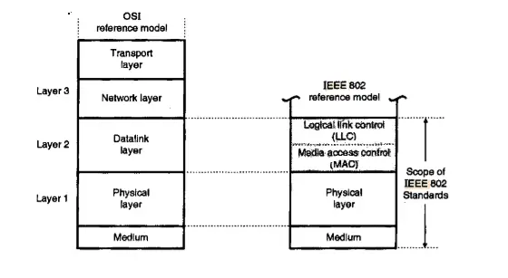
The IEEE has subdivided the data link layer into two sublayers i.e logical link control (LLC) and media access control (MAC).
In IEEE Project 802, flow control, error control, and part of the framing duties are collected into one sublayer called the logical link control. Framing is normally handled in both the LLC sublayer and the MAC sublayer.
Frames in IEEE format (traditional IEEE 802.3)
Now let us understand the frame format in ethernet :

Preamble: The first field of the 802.3 frames contains 7 bytes (56 bits) of alternating 0’s and 1’s that alerts the receiving system to the coming frame and enables it to synchronize its input timing.
Start frame delimiter (SFD): It is the second field (1 byte: 10101011) signals the beginning of the frame. The SFD warns the station or stations that this is the last chance for synchronization. It is a simple sequence of alternating 0’s and 1’s.
Destination address (DA): The DA field is 6 bytes and contains the physical address of the destination station or stations to receive the packet.
Source address (SA): The SA field is of 6 bytes and contains the physical address of the sender of the packet.
Length or type: This field can be defined as a type field or length field. The original Ethernet used this field as the type field in order to define the upper-layer protocol using the MAC frame.
Data: This field mainly carries data encapsulated from the upper-layer protocols.
CRC: The last field generally contains error detection information.
Frame Length in IEEE format
There is a restriction imposed on the minimum and maximum length of the frame of the Ethernet. The minimum frame length is 512 bits or 64 bytes and the maximum frame length is 12,144 bits or 1518 bytes.
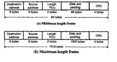
The standard defines the maximum length of a frame (without preamble and SFD field) as 1518 bytes. If we subtract the 18 bytes of header and trailer, the maximum length of the payload is 1500 bytes.
Addressing in IEEE Format
Each station on an Ethernet network (such as a PC, workstation, or printer) has its own network interface card (NIC). The NIC fits inside the station and provides the station with a 6-byte physical address.
The destination address can be one of the following three types:
Unicast destination address : Uni means one. So this type of address defines only one destination and the relation between the sender and the receiver is one-to-one. The frame sent by the sender is meant only for one particular receiver.
Multicast destination address : Multi means many, so this type of address defines a group of destination addresses to which the same message is to be delivered. Thus the sender-receiver relation is one too many.
Broadcast address : The broadcasting process is the process in which the sender transmits and all others receive or listen. This type of destination address is a special case of a multicast address in which all stations are destinations.
Token Bus ( IEEE 802.4 )
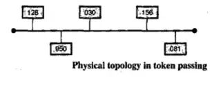
The IEEE 802.4 standard for media access control (MAC) is known as Token bus. Logically the interconnected stations form a ring. Each station knows its own identification number and the identity of the stations preceding and following it.
The sequence number and the physical location of a station on the bus are not related to each other. At any time, the station which holds the token only can transmit its data frames on the bus. Every frame contains the source and destination addresses.
As soon as the transmission time of a station is over, it passes the token to the next station in the logical sequence. That station is allowed to transmit its data now. Likewise, the token is circulated over the entire ring to all the stations.
The frame format as specified by IEEE 802.4 is as shown in Fig :
Token Ring System (IEEE 802.5)
A token ring system is as shown in Fig. It consists of a number of stations connected to the ring through a Ring Interface Unit (RIU). The RIU is basically a repeater, therefore it regenerates the received data frames and sends them to the next station after some delay.
The token is passed from one station to the other round the ring. The sequence of token passing is dependent on the physical location of the stations connected to the ring. It is not dependent on the logical numbers as in the case of the token bus system.

The IEEE 802.5 has standardized the formats for the token frame and data frame. They are as shown in the fig above.
In the next post, we will see the next related topic i.e FDDI. So stay tuned…

Aric is a tech enthusiast , who love to write about the tech related products and ‘How To’ blogs . IT Engineer by profession , right now working in the Automation field in a Software product company . The other hobbies includes singing , trekking and writing blogs .

