Data Link Layer – High Level Data Link Control (HDLC) Protocol
In the previous posts, we have already seen the sliding window and stop – wait protocols of the data link layer. Now we gonna understand the HDLC (High Level Data Link Control) protocol in DLL .
High-level Data Link Control (HDLC) is a bit-oriented protocol for communication over point-to-point and multipoint links and based upon the ARQ mechanism seen in the previous posts. It is the most widely accepted data link layer protocol. It has the advantages of flexibility, adaptability, reliability, and efficiency of operation .
There will be two transfer modes in HDLC i.e the normal response mode (NRM) and asynchronous balanced mode (ABM).
In the normal response mode (NRM), the station configuration is unbalanced. We have only one primary station and multiple secondary stations. A primary station can send commands whereas a secondary station can only respond.
In asynchronous balanced mode (ABM), the configuration is balanced. The link is point-to-point, and each station can function as a primary and a secondary (acting as peers).
For the HDLC protocol, the following three types of stations have been defined.
Primary Station : A primary station takes care of data link management. The frames sent by a primary station are called commands.
Secondary Station : A secondary station operates under the control of a primary station. The frames sent by the secondary station are called responses.
Combined Station : A combined station can act as primary as well as secondary stations. Therefore it can send both commands and responses.
Frames in HDLC
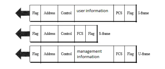
To provide the flexibility necessary to support all the options possible in the modes and configurations just described, HDLC defines three types of frames i.e information frames (I-frames), supervisory frames (S-frames), and unnumbered frames (V-frames).
I-frames are used to transport user data and control information relating to user data (piggybacking). S-frames are used only to transport control information. V-frames are reserved for system management.

Operating modes for data transfer in HDLC
In HDLC both synchronous and asynchronous modes of communication are permitted. Following modes of operation are possible for data transfer :
Normal response mode (NRM) : It is a synchronous mode of communication. This mode is suitable for point-to-point as well as point-to-multipoint configurations.
Asynchronous Response Mode (ARM) : This mode is used for communication between primary and secondary stations. As the name indicates it is an asynchronous mode o(communication.
Asynchronous Balanced Mode (ABM) : This mode is applicable to the point to point communication between two combined station. As both these stations are combined stations, they are capable of link management functions.
Frame Structure in HDLC
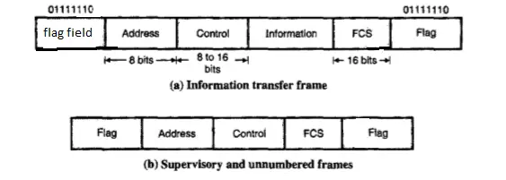
Flag field : The flag field of an HDLC frame is an 8-bit sequence with the bit pattern 01111110 that identifies both the beginning and the end of a frame .

Address field : The second field of an HDLC frame contains the address of the secondary station. Address field consists of 8 bits hence it is capable of addressing 256 addresses.
Control field : The control field is a 1- or 2-byte segment of the frame used for flow and error control. The interpretation of the bits in this field depends on the frame type. The control field usually consists of 8 bits but the number of bits can be extended to 16. It contains different data for each of the different types of frames i.e I frames, S frames and V frames.

Information field : The information field contains the user’s data from the network layer or management information. It consists of the user’s data bits and it is completely transparent.
FCS field : The frame check sequence (FCS) is basically the HDLC error detection field. It can contain either a 2 or 4 byte.This is a 16 bit field that is used for the detection of errors in the address, control, and information field.
Transparency In HDLC
The data field of HDLC frame is capable of carrying text and non-text information. The examples of non-text information is audio, video, graphics etc . If the data field of an HDLC frame contains the pattern 01111110 which is reserved for the flag field, then the receiver will treat that sequence as the end flag.
Bit Stuffing in HDLC
Bit stuffing is used to overcome the lack of data transparency. In HDLC, transparency is achieved by ensuring that the unique flag sequence (01111110) does not appear in the address, control, information, and FCS fields.
At the transmitter, an extra ‘0’ bit is inserted after five consecutive 1 ‘s occurring anywhere after the opening flag and before the closing flag.
At the receiver, the extra ‘0’ bit following five consecutive “1” is deleted. This technique is called “zero stuffing” or bit stuffing.
The bit stuffing is not done for three operating conditions. First is when the bit sequence is really a flag, second is when the transmission is being aborted, and the third is when the channel is idle.
Point to Point Protocol (PPP)
Although HDLC is a general protocol that can be used in the case of both point-to-point and multipoint configurations, one of the most basic protocols for point-to-point access is the Point-to-Point Protocol (PPP).
PPP defines the basic format of the frame to be exchanged between devices. PPP defines how any network layer data are encapsulated in the data link frame.
PPP also provides network address configuration. This is particularly useful when any home user needs a temporary network address to connect to the Internet.
PPP is a data link layer protocol. However, it uses a set of other protocols in order to carry out the following operations :
- Link-establishment
- Authenticating the involved parties
- Carry the network layer data
The PPP protocol can operate over a variety of point to point transmission links such as ADSL and SONET .
This protocol is used by a lot of Internet users to connect their home computers to the server of an Internet service provider (ISP). The PPP is used for controlling and managing the data transfer.
This protocol was designed for users who wanted to connect their computer system through a telephone line to.the computer of an Internet service provider to access internet.
In the next post , we will understand the functioning of the MAC layer in detail. So stay tuned…

Aric is a tech enthusiast , who love to write about the tech related products and ‘How To’ blogs . IT Engineer by profession , right now working in the Automation field in a Software product company . The other hobbies includes singing , trekking and writing blogs .


