Control System – Compensator Design
We all know that control systems are designed to perform specific tasks. In order to provide suitable performances, it is required to alter or adjust the control system design.This alteration (adjustment) of a control system is called compensation. The device used for the same is called compensator.
Standard compensators
The three standard compensator designs (apart from gain adjustment) are
- Lead compensator
- Lag compensator
- Lag-lead compensator
Lead compensator
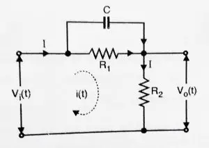
The Lead compensator can be realized by an electric network as shown below:

Let us now derive transfer function assuming impedance to be zero and the output load impedance to be infinite.
![]()
The equation for output is :
![]()
Take Laplace transform of above equations,
![]()
![]()
Taking ratio of ![]() (s) and
(s) and ![]() (s) to obtain transfer function,
(s) to obtain transfer function,
![]() =
= ![]() (on simplifying)
(on simplifying)
Dividing numerator and denominator by ![]() and defining ‘ τ =
and defining ‘ τ = ![]() and α =
and α = ![]() we get,
we get,
![]() =
= ![]() ,
,
Thus the transfer function is given as
![]() =
= ![]() ,
,
Now for the equation of phase, we replace s by jω.
![]() (jω) =
(jω) = ![]()
Hence , phase = ∠![]() (jω) =
(jω) = ![]() =
= ![]() –
– ![]() ,
,
Since ![]() < 1 , the phase of (jω) will be positive for all ω
< 1 , the phase of (jω) will be positive for all ω ![]() 0 . Thus this network is called a phase lead network.
0 . Thus this network is called a phase lead network.
Advantages of lead compensator
- Increases system bandwidth.
- It improves the dynamic response of the system.
Now , next we shall study about Lag compensators.
Lag compensators
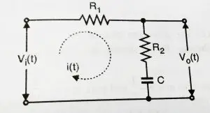
A lag compensator can be realized by an electrical network shown below:

Now we will derive the transfer function of lag network:
On applying KVL, we can obtain input and output equations,
![]() (t) =
(t) = ![]() i(t) +
i(t) + ![]() i(t) +
i(t) + ![]() dt ,
dt ,
The equation for output is
![]() (t) =
(t) = ![]() i(t) +
i(t) + ![]() dt
dt
Taking Laplace transform of equations,
![]() (s) =
(s) = ![]() I(s) +
I(s) + ![]() I(s) +
I(s) + ![]() ,
,
![]() (s) =
(s) = ![]() I(s) +
I(s) + ![]()
Taking ratio of output and input
![]() =
= ![]()
Now, defining τ = ![]() and
and ![]() =
= ![]() ,
,
The transfer function for Lag compensator will become,
![]() (s) =
(s) = ![]() ,
,
Now for the equation of phase, we replace s by jω.
![]() (jω) =
(jω) = ![]() ,
,
phase = ∠![]() (jω) =
(jω) = ![]() =
= ![]() –
– ![]() ,
,
since ![]() , the phase of
, the phase of ![]() (jω) will be negative for all ω
(jω) will be negative for all ω ![]() 0 . Thus this network is called a phase lag network.
0 . Thus this network is called a phase lag network.
Advantages of lag compensator
- Improves steady state accuracy
- Suppresses high frequency noise
Lag – lead Compensator
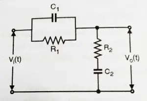
The lag – lead network can be realized by a single electric network (refer figure shown below). It is basically a combination of both lag and lead network.

Now we will find out the transfer function of the above network as shown below:
We first apply KVL to obtain input and output equations:
![]() (t) =
(t) = ![]() ,
,
And The equation for output is
![]() (t) =
(t) = ![]() i(t) +
i(t) + ![]() ,
,
Now we need to take Laplace transform for both the above equation:
![]() (s) = [
(s) = [![]() ]I(s) ,
]I(s) ,
And ![]() (s) = [
(s) = [![]() ] I(s) ,
] I(s) ,
Taking ratio of output and input equations,
![]() =
= ![Rendered by QuickLaTeX.com \frac { R_{ 2 }+\frac { 1 }{ sC_{ 2 } } I(s) }{ [\frac { { R }_{ 1 }\quad \times \quad \frac { 1 }{ s{ C }_{ 1 } } }{ { R }_{ 1 }\quad +\quad \frac { 1 }{ s{ C }_{ 1 } } } \quad +\quad { R }_{ 2 }\quad +\quad \frac { 1 }{ s{ C }_{ 2 } } ]I(s) }](https://electronicsguide4u.com/wp-content/ql-cache/quicklatex.com-63a27cf4933b147156d5596631749b57_l3.png) ,
,
On solving and simplifying we get ,
![]() =
= ![]() ,
,
Dividing by ![]() to both numerator and denominator we get,
to both numerator and denominator we get,
![]() =
= ![]() ,
,
Now defining ![]() =
= ![]() ,
, ![]() =
= ![]() ,
,
![]() =
= ![]() ,
,
And ![]() =
= ![]() ,
,
We get the transfer function of lag – lead compensator as :
![]() =
= ![]() ;
; ![]() > 1 ,
> 1 ,
Design of Compensators using Bode plot:
For design purpose, it is best to work with Bode plot.We know that if open loop gain is altered , then the magnitude curve further moves down or up without altering the slope of the given curve and also the phase curve will remains as it is. The common approach to design compensators using bode plot involves following steps:
- Plot the magnitude and phase curve of the uncompensated open loop system.
- Check the specification of the phase margin and gain margin.
- If the specifications of GM and PM are not satisfied then use a suitable compensator.
- Determine reshaped open-loop transfer function using the selected compensator.
- Check other requirements to meet the specification .
- Plot Bode plot using reshaped open-loop transfer function.
Rate feedback Compensation
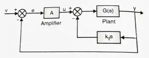
Root locus helps us to point out the capability of rate feedback . Rate feedback is given by the equation:
![]() (s) =
(s) = ![]() t
t
You may refer the below diagram:

This feedback system provides the ability to vary three parameters namely : A, k and ![]() . For achieving better-specified performance, there must be a large number of variables inserted into a system. Design will become much more complex. There are two design methods for the design of the control system with rate feedback. One based on the single point loci and other on multiple parameter loci.
. For achieving better-specified performance, there must be a large number of variables inserted into a system. Design will become much more complex. There are two design methods for the design of the control system with rate feedback. One based on the single point loci and other on multiple parameter loci.
A tachometer is one of the rate feedback devices. And the other one is rate gyro. Rate gyro is commonly used in aircraft autopilot system. Velocity feedback using a tachometer is very commonly used in position servo systems.

Aric is a tech enthusiast , who love to write about the tech related products and ‘How To’ blogs . IT Engineer by profession , right now working in the Automation field in a Software product company . The other hobbies includes singing , trekking and writing blogs .
